Vertical farming on your balcony
Using the space that you have efficiently
Imagine this: You like plants. Like a lot. You like to grow them because they look pretty, they are good for the environment, they can produce food for you and they are in many cases the key ingredient for your favorite beverage. But you face this one problem: you life in a place without much space. When you think about vegetable production the first thing that comes to your mind are fields. Maybe you remember the last time you flew over some rural area on your way to your holidays. From up there everything looks rather two dimensional. Right? Fields of corn, wheat, onion or lettuces with one plant after the other in long lines forming a matrix on a large patch of land. But now you think to yourself: We're but three dimensional! Why not use this vertical space that lies unused for 16km until we cross the outer layers of our atmosphere?! The sky's the limit :). Here on our humble balcony I wanted to start an experiment to see if I can use the limited space at our disposal as efficient as possible. I usually grow tomatoes. These are easy and with a spiral stick a ground dwelling shrub becomes a nice and magnificient tomato bush reaching two meters in height over the growing season with ease. Mini cucumbers are also rather simple. A wooden trellis to climb on and the plant goes up into the vertical dimension. Nice and straight forward so far. Give plant something to climb, plant climbs. But now comes this lettuce we've been talking about already. A lettuce head is a lettuce head. It won't grow up the wall just by giving it a way to climb. You have to plant it in a vertical system were it will do it's job of growing. Because I like cheap electronics and I like to tinker with them I wanted to build something that combines the worlds of plant growing and tinkering. Enter the solar powered, vertical farming, hydroponics system for the balcony!
Hydroponic systems
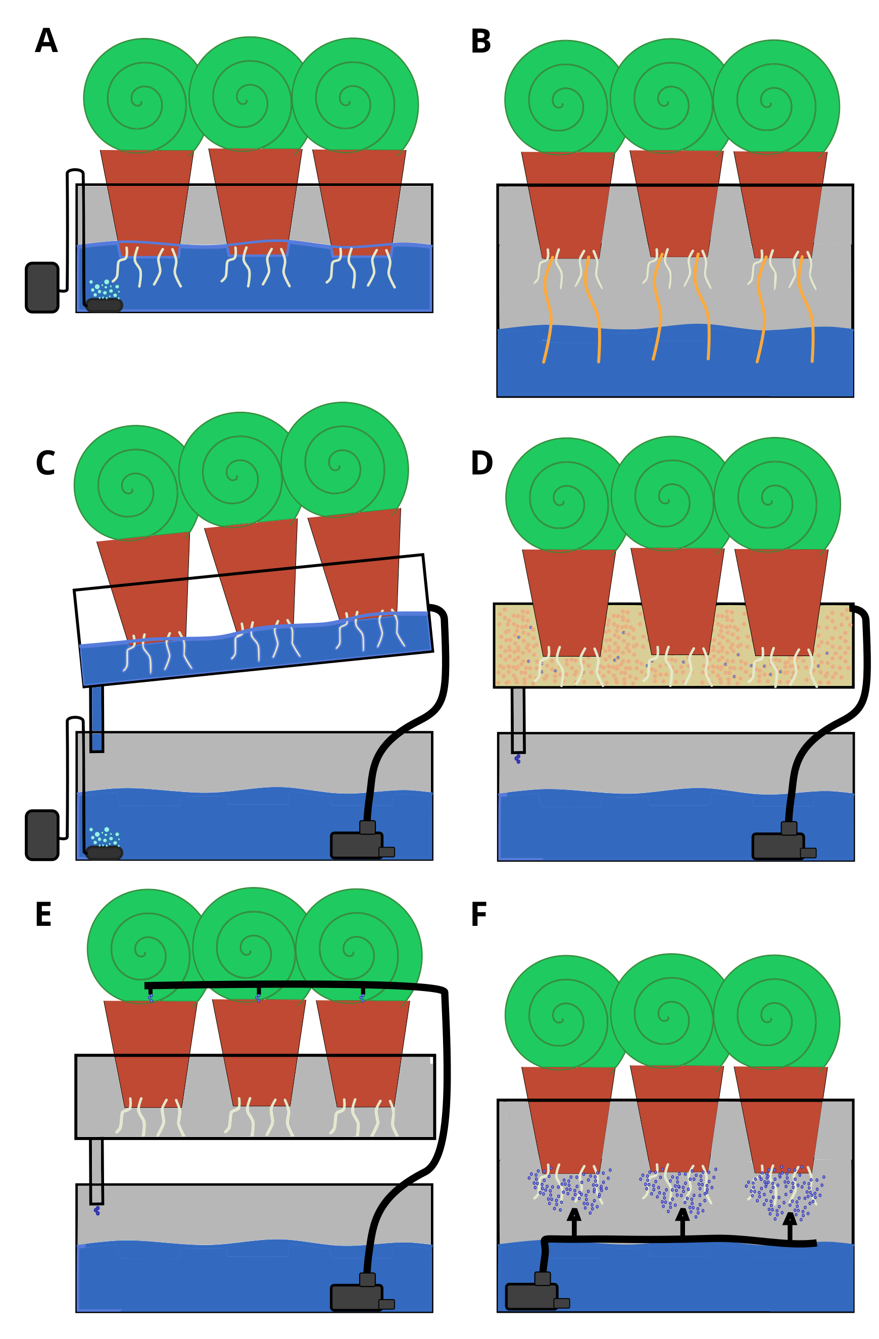
Over the last decades hydroponics has grown into quite the sophisticated way of growing plants by using nutrient solutions surrounding the roots / root balls rather than using soil. Like leaves, roots suffocate when they are submerged in water. Therefore many ways of hydroponics are available that allow aeration of the root system. Plants are germinated in a substrate like rock-wool, perlite or pressed coconut coir. After germination, the seedlings are transferred to the hydroponics system. The easiest forms of hydroponics are the "Deep Water Culture" (A) and the "Wick System" (B). In the first system the germination media is submerged into the nutrient solution which is aerated by a air stone connected to a aquarium air pump. The "Wick System" is realized by using a wick dangling from the germination media into the nutrient solution. Capillary forces will suck up the nutrient solution into the germination media. Other systems require a water pump to allow the circulation of the nutrient solution. The "Nutrient Film Technique" (C), "Flood and Ebb" (D) and "Drip System" (E) are part of the circulation systems. The "Nutrient Film Technique" requires, like the "Deep Water Culture", aeration of the nutrient solution. The water flows past the root ball and wets it allowing nutrient uptake by the roots. The "Flood and Ebb" solution floods the root ball and slowly lets it drain similar to the "Nutrient Film Technique". As the name implies the "Drip System" drips the right amount of nutrient solution onto the root ball. The last system on the list is the "Aeroponics" (F) setup. Here the nutrient solution is applied to the roots via a fine mist allowing plenty of air and nutrients around the roots.
The vertical hydroponic prototype-system
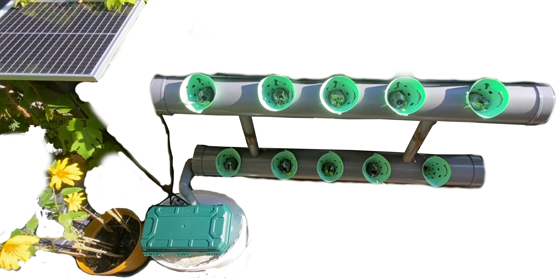
From the above listed hydroponic options I chose a combination of the "Drip System" and the "Nutrient Film Technique". I combined this with a very simple vertical setup consisting of two PVC pipes (diameter 11cm) stacked on top of each other with 8cm holes in them to hold the plants. The two horizontal pipes are stacked using two pipes with a diameter of 3.3cm. The circulated nutrient solution is stored in a bucket below the system.
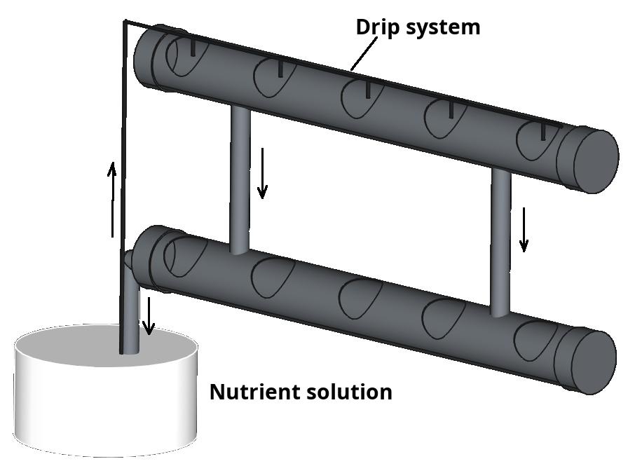
Next to their structural component the two vertical pipes allow the nutrient solution to flow from the top to the bottom horizontal pipe. They are inserted 2cm deep into the top pipe to retain some of the nutrient solution so that the roots won't dry out in later growth stages of the lettuces. The pipe allowing the back-flow from the lower horizontal pipe into the reservoir is just like the vertical pipes 2cm lifted to retain some nutrient solution in the lower gwoth pipe. As I haven't added any aeration in the setup I'm hoping that the circulation of the water through the drip system and the flow back to the bucket is enough to get some air into the nutrient solution.
A schematic of the whole system is shown on the right. Flow of the nutrient solution is indicated by arrows. As reservoir I chose an inexpensive white paint bucket in which I drilled holes for the back-flow pipe, the electronics (temperature and total dissolved solids (TDS) sensors) and hose of the submerged pump. Sides of the plant pipes are sealed with fitting PVC pipe end-caps. For draining the system at the end of the season or for cleaning two 3.3cm holes are drilled in the end-caps of both plant growth pipes which are sealed with removable caps.
I usually germinate my plants in pressed coconut coir. To hold the germinated plants later in the hydroponics system I 3D printed cones for hydroponics posted on printables.com by the user @netaes_263443 - Hydroponic System Planting Cone. The cones are printed as flat sheets which are afterwards rolled into their shape. I printed them in PLA (not the most durable plastic i know) and used a hairdryer at the end to keep the plastic soft enough to roll it into the cone shape. They are now in their second season and I don't see any degradation of the PLA. I do appreciate the design of these cones as they have retention flaps which hold the cones securely in their place in the 8cm holes.
The nutrient solution
When I first started to look into this I didn't want to spent too much
time on this topic. Therefore I went through listings of hydroponic nutrient
solutions on amazon. I soon realized that everything there is tailord to
a certain type of grower group that had nothing to do with lettuce or
other vegetables... :) Therefore I broadend my search and I ended up with
the company "Masterblend". There I found a hydroponic fertilizer
which is composed of the "Masterblend 4-18-38" (4% Nitrogen, 18% Phosphate,
38% Potassium), magnesium sulfate (MgS04) and calcium nitrate (Ca(NO3)2). The mix
of these components for 10 L for leafy greens is indicated in the table below:
| Component | Amount |
|---|---|
| Masterblend 4-18-38 | 5.3 g |
| Calcium nitrate | 5.3 g |
| Magnesium sulfate | 2.6 g |
| Water | 10 L |
After adding this to the reservoir the TDS sensor indicated a value of 600 to 700 ppm which is perfectly inbetween the recommended 560 - 800 ppm for growing lettuce in hydroponics. All in all this fertilizer is doing a great job as the lettuces were growing very well. It is easy to handle as it easily dissolves in water and the amount that I bought is enough for around 470 L of solution.
Electronics for circulating and analyzing the nutrient solution
An overview of the whole system is shown below. It is designed to be self-sustained with a solar panel (25W) charging a lithium-iron-phosphate (LiFePO4) battery via a cheap solar charge-controller which then powers an aquarium pump.
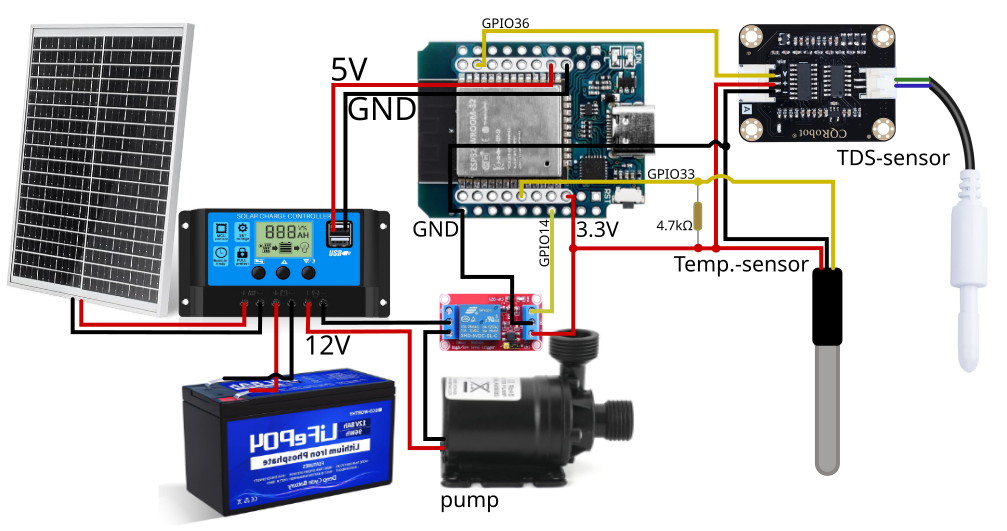
The charge-controller has a 12V output which is used to power the submerged pump. Additionally the charge-controller has two USB A ports to power two 5V devices. One of these outputs is used to power the Wemos D1 mini ESP32. This microcontroller is the brains of the whole system and is used to switch the pump on and off using a 3.3V switchable relay. Furthermore it collects sensor data from the hydroponics nutrient solution. So far this data is limited to the temperature of the solution using the Dallas DS18B20 temperature sensor and a total dissolved solids (TDS) sensor (parts per million (PPM)) which gives an indication about nutrient availability for the growing plants. In the future I'm planning to add also a pH sensor to get insight into this important parameter as well. But so far I havn't found a cheap sensor that can be submerged for a prolonged period of time.
Battery, charge controller, microcontroller, relay and TDS sensor PCB are safely stored in a outdoor enclosure rated at IP54 (protection against "splashing of water" (5) and "water jets" (4) from all sides of the enclosure IP codes). The two probes for temperature and TDS are floating inside the bucket on top of the nutrient solution using a piece of styrofoam and the pump is submerged with a hose attached to it. Below is a picture of how the system looks like with lettuce plants in their early stages.
List of used components
I'm listing here the components I used for building the whole system. I'm not including connectors (e.g. PH type connectors for PCB mount, Wago clamps), crimping tools (e.g. for wire end ferrules or for PH connectors) and wires (22 AWG for low power components, 16 AWG (rated for 3.7A) for the solar components (12V, 25W) and the pump (12V, 19W)) as this might differ for your setup.
Waterproof box for outdoor use
Solar panel 25W (12V)
8Ah LiFePO4 battery
Solar charge controller 30A (12V / 24V)
Water pump (12V)
Wemos D1 mini ESP32
TDS sensor (CQRobot)
Dallas DS18B20 temperature sensor (water proof)
One channel relay 5V (rated for 10A 30VDC)
Through-hole prototype pcb
Resitors (through hole type)
- 4.7kΩ for 1-wire Dallas temperature sensor
- 200kΩ for voltage devider for 12V
- 20kΩ for voltage devider for 12V
Home assistant integration
I have integrated the whole system into Home Assistant using ESPhome which lets me easily monitor the status of the whole system at any given moment. ESPhome makes your life extremely easy and Home Assistant is just incredible for it's versatility. I will not explain the process of flashing the firmware using ESPhome to the Wemos D1 mini ESP32 board. People who are interested in this and are not sure how to are welcome to visit the official ESPhome documentation at: ESPhome - getting started from Home Assistant. The Wemos D1 mini ESP32 like the original Wemos D1 mini is very user-friendly as it contains all components for establishing a serial connection using the onboard micro-usb port (i know sadly no USB-C...) with the device running Home Assistant. I usually connect the board directly to my Raspberry Pi running Home Assistant to flash it using the ESPhome setup wizard. After that I enjoy the over-the-air (OTA) wireless connection for logs, firmware updates and code uploads :) Just nice and easy.
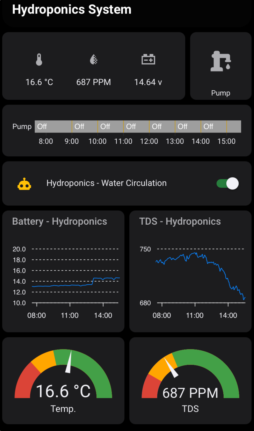
Home Assistant allows you to make the most beautiful dashboards to visualize your sensor data. A little bit of playing around and learning how things are done allows you to create something like the dashboard shown on the left. I have a quick overview of the most current sensor readings and a switch to manually trigger the water circulation. Below that is a history-graph telling me if the water pump was turned on. Another amazing thing of Home Assistant is the simplicity of creating an automation. In this case it is the water circulation which is timed for every full hour, for one minute, two hours after and two hours before sunrise or sunset, if the battery voltage is above 12.4V. This automation can be turned on and off with a toggle switch depending on if the hydroponics system is in use or not. Below this, some long-term data for battery voltage and TDS PPM are shown as a line graph. As there are optimums for the growth in terms of temperature and TDS PPM for lettuce a gauge-graph is shown with the optimum for both colored in green the intermediate in yellow and the bad in red. Both YAML codes for the dashboard and the automation are listed and described below together with the YAML for the ESPhome setup of the Wemos D1 mini ESP32.
The first harvest
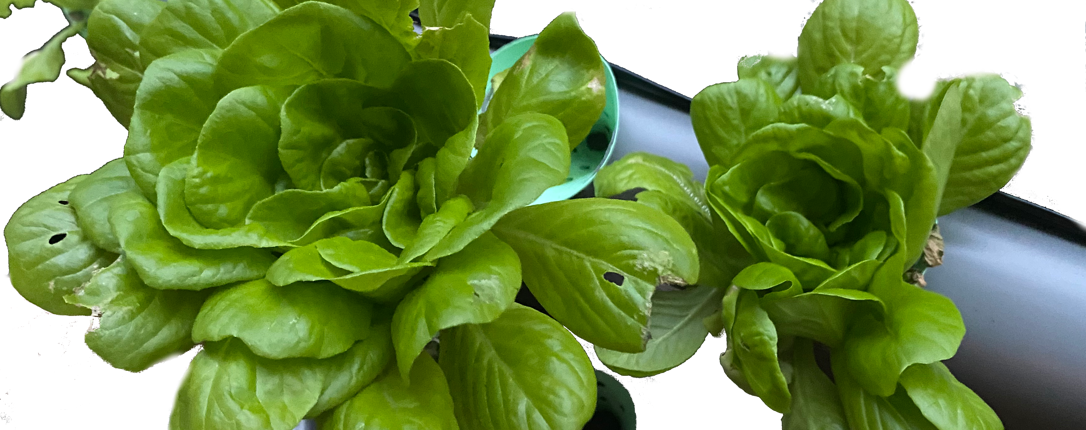
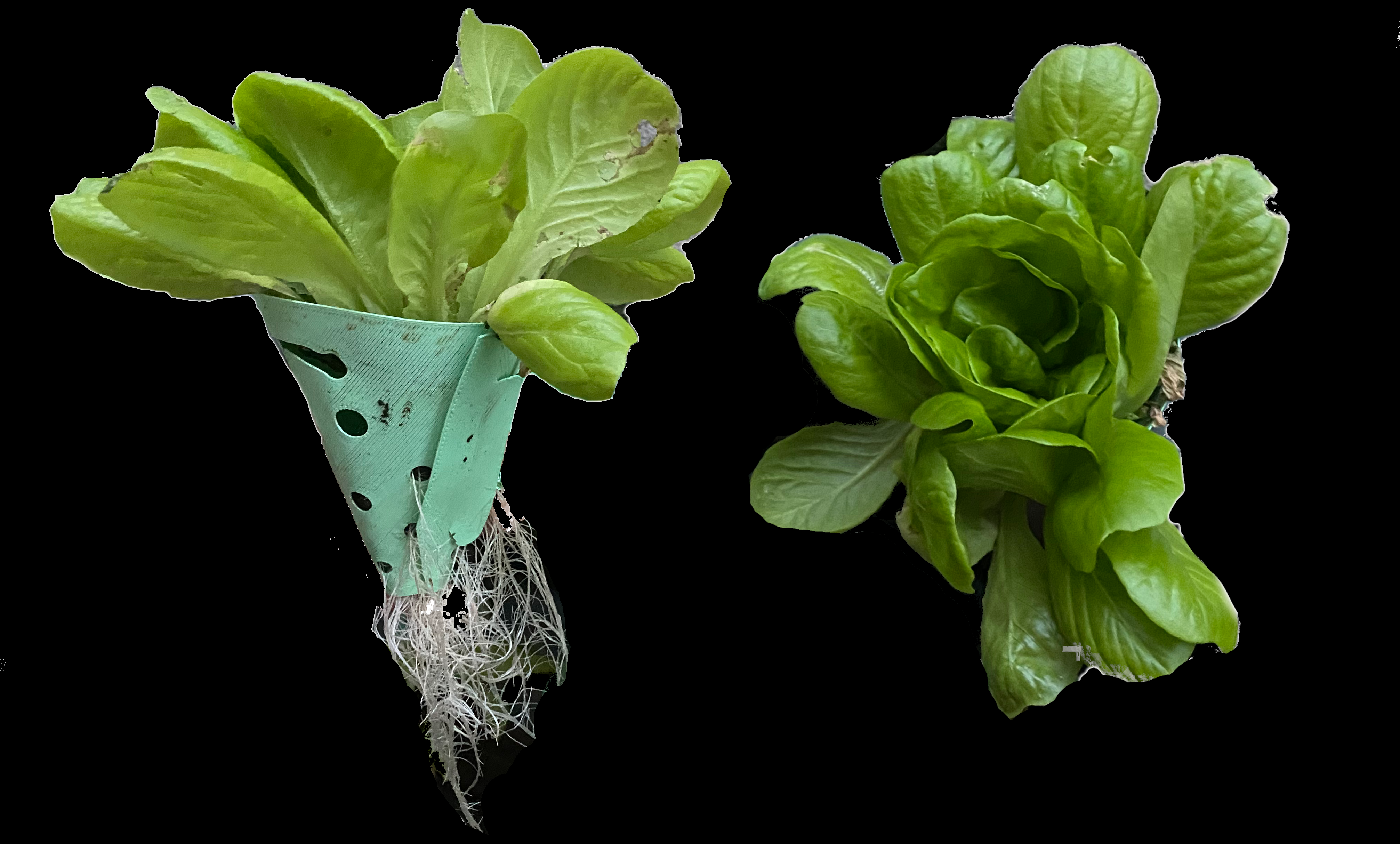
The hydroponics system as is surely won't beat any speed records in growing lettuce. In the initial growth experiment it took 42 days for the lettuces to be big enough for harvest. This first try also showed that there are lettuce varieties that don't appreciate the hydroponic system as much as others. Butterhead type lettuce did not grow as expected. Leaves got elongated maybe due to too high nutrient availability and a stormy day finished these plants off by breaking the majority of the leaves. Multi-leaf type lettuce on the other hand was doing well. It formed a nice head and we enjoyed a few of these as you can see in the image below. Roots of the plants were nice and white just the way they should be. In this first trail the plants were harvested too early. They could have easily doubled in size in my opinion. But excitement got the better of me :).
The code
ESPhome integration of the microcontroller and the sensors
Below I will describe the ESPhome setup of the different sensors and the calculations needed to get to the PPM readout of the TDS sensor. I divided the code into chunks to better explain it. For ESPhome the pieces have to be put together below the 'captive portal:' section. As a microcontroller I used the Wemos D1 mini ESP32 version flashed with ESPhome using Home Assistant. This should also work with something less powerful like the original Wemos D1 mini with a ESP8266. The first thing to define is the 1-Wire Bus for the read-out of the Dallas DS18B20 temperature sensor. This temperature sensor needs next to this software setup a 4.7kΩ pull-up resistor between the data-line and 3.3V as you can see in the electronics overview from above (ESPhome reference).
        captive_portal:

        # One-wire bus for Dallas DS18B20
        one_wire:
          - platform: gpio
            pin: GPIO33
            id: temp_1wire
The next step is to define the sensors themselves. First off is the Dallas temperature sensor. This sensor will measure the temperature of the nutrient solution. This value is important as it will be used later for compensating the influence of temperature on the conductivity of the nutrient solution. With rising temperature the solution will become more conductive which will cause false readouts by the TDS sensor. The code below uses the ESPhome predefined 'dallas_temp' setup, names the performed measurement 'probe01' and collects sensor data every 2min.
        # Section of sensors:
        sensor:
        # Temperature In °C from the Dallas DS18B20
          - platform: dallas_temp
            id: probe01
            name: temperature
            update_interval: 120s
The TDS sensor measures conductivity of the solution. Therefore, the readout is a changing voltage which ranges between 0 to 2.3V for the used TDS sensor. We need to read this through an analog-to-digital converter (ADC) pin of the ESP32 microcontroller. To do this check the pin-out of the respective board you're using. Once you found a pin that can do ADC you can specify the ESPhome setup 'adc' and the GPIO pin. For the Wemos D1 mini ESP32 I chose the GPIO33 pin to read the raw voltage from the TDS sensor. The interval for measurement is again 2min.
        # Raw TDS Reading
          - platform: adc
            pin: GPIO36
            name: TDS 01 Raw
            attenuation: auto # only for ESP32
            id: tds01_raw
            update_interval: 120s
            unit_of_measurement: v
            accuracy_decimals: 3
            internal: true
In this part the measured raw TDS voltage is temperature compensated. The temperature of the Dallas sensor is used to calculate the TDS compensated voltage (TCV). The ESPhome 'template' is used to define this sensor value. We have to define the unit of measurement as being voltage 'v' and use the scary formula. Lets break it down:
- id(tds01_raw).state = the raw TDS voltage
- id(probe01).state = the Dallas measured temperature
- 0.02 = a factor depending on what solution is being measured (Temp compensate electrical conductivity)
- 25.0 = the temperature against which the compensation will be calculated. At 25C the correction is 1 (https://www.aqion.de/site/112)
So the actual formula is: TCV = TDS raw (V) / (1 + (0.02 * (Dallas Temperature - 25C))). Again this is measured every 2min.
        # Temperature Compensated Voltage
          - platform: template
            name: TDS 01 TCV
            id: temp01_comp_v
            unit_of_measurement: v
            accuracy_decimals: 3
            lambda: 'return ((id(tds01_raw).state) / (1 + (0.02 * ((id(probe01).state) - 25.0))));'
            update_interval: 120s
            internal: true
Now finally the TDS value in PPM is calculated using the temperature compensated conductivity (TCV). The formula used is the formula supplied by the seller of the TDS sensor CQ-Robot - TDS (Total Dissolved Solids) Meter Sensor SKU: CQRSENTDS01. The formula is a "cubic polynomial curve fit: TDS = a*x^3 + b*x^2 + c*x". This formula should be determined by measuring different concentrations of the nutrient solution and then fit a the polynomial curve to the data observed. I went the lazy route (for now) and just used the manufacturer supplied values.
        # Temperature Compensated TDS
          - platform: template
            name: TDS-01
            unit_of_measurement: PPM
            state_class: measurement
            accuracy_decimals: 0
            update_interval: 120s
            lambda: return (133.42*(id(temp01_comp_v).state)*(id(temp01_comp_v).state)*(id(temp01_comp_v).state) - 255.86*(id(temp01_comp_v).state)*(id(temp01_comp_v).state) + 857.39*(id(temp01_comp_v).state))*0.5;
            filters:
              - median:
                  window_size: 4
                  send_every: 2
                  send_first_at: 1
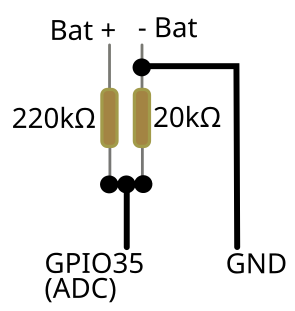
As this system is running on solar power I was interested in the voltage of the lithium battery that I added to keep everything running. I chose a 8Ah battery in combination with 25W solar panel. I did not know if this would be sufficient to run the whole system for multiple days with little to no sun. It turns out that the 8Ah battery can keep the system running for up to 3 days without any sun. To see the voltage over time I added a voltage divider to read the scaled down battery voltage at one of the ADC pins like before for the TDS sensor. In this case I used a 220kΩ resistor connected to the positive lead of the battery and 20kΩ resistor connected to the negative lead. This would scale the voltage to 1 when the battery is at 12V. A full 12V LiFePO4 battery has a voltage of 13.6V at rest and 14.6V at charging. So This combination of resistors seemd to be a good choice as this meant 1.22V as measurement on the ADC pin which can handle 0 - 3.3V. Even if the voltage would somehow spike beyond what is normal this setup should keep the voltage on the GPIO pin in a safe range.
        # Raw voltage divider battery reading
          - platform: adc
            pin: GPIO35
            name: Bat 01 Raw
            attenuation: 6db # only for ESP32
            id: bat01_raw
            update_interval: 120s
            unit_of_measurement: v
            accuracy_decimals: 3
            internal: true

        # Actual voltage of battery
          - platform: template
            name: Bat 01
            id: bat01_comp
            unit_of_measurement: v
            state_class: measurement
            accuracy_decimals: 2
            lambda: |-
              float r1 = 220000;
              float r2 = 20000;
              float vPow = 3.3;
              float voltage = (id(bat01_raw).state) / (r2 / (r2 + r1));
              return voltage;
            update_interval: 120s
Last but not least the switch. This entity controls the relay which turns on and off the submerged pump allowing the circulation of the nutrient solution. The only thing that we have to specify for the GPIO pin is 'inverted: true' as this switch is by default turned off.
        switch:
          - platform: gpio
            name: Water Pump
            pin:
              number: GPIO14
              inverted: true
The water circulation automation
This YAML code is the water circulation automation mentioned before. It is triggered every hour with the following conditions:
- Measured battery voltage is above 12.4V
- It is two hours after sunrise
- It is two hours before sunset
If these conditions are fulfilled the pump is switched on for 1 min and then turned off again. The device_id and entity_id variables have to be changed accordingly
alias: Hydroponics - Water Circulation
description: >-
  Circulates the water of the hydroponics system: every hour between sunrise and
  sunset, 1 min of pump activation
mode: single
triggers:
  - hours: /1
    trigger: time_pattern
conditions:
  - condition: and
    conditions:
      - type: is_value
        condition: device
        device_id: xxx #<- add your device_id
        entity_id: xxx #<- add your entity_id
        domain: sensor
        above: 12.4
      - condition: sun
        after: sunrise
        before: sunset
        before_offset: -02:00:00
        after_offset: 02:00:00
actions:
  - metadata: {}
    data: {}
    target:
      entity_id: switch.hydroponics_system_water_pump
    action: switch.turn_on
  - delay:
      hours: 0
      minutes: 1
      seconds: 0
      milliseconds: 0
  - metadata: {}
    data: {}
    target:
      entity_id: switch.hydroponics_system_water_pump
    action: switch.turn_off
The Home Assistant dashboard
The Home Assistant dashboard shown above can be recreated using the following YAML code. It requires the installation of the apexcharts cards from HACS. Other than that everything should be working with the standard Home Assistant love-lace cards.
icon: mdi:sprout-outline
theme: iOS Dark Mode
cards:
  - type: markdown
    content: |-
      ##
      ## Hydroponics System
    theme: ios-dark-mode
  - type: horizontal-stack
    cards:
      - show_name: false
        show_icon: true
        show_state: true
        type: glance
        state_color: true
        entities:
          - entity: sensor.hydroponics_system_temperature
          - entity: sensor.hydroponics_system_tds_01
          - entity: sensor.hydroponics_system_bat_01
      - type: custom:button-card
        entity: switch.hydroponics_system_water_pump
        theme: ios-dark-mode
        name: Pump
        styles:
          card:
            - width: 100px
            - height: 110px
            - font-size: 12px
  - type: history-graph
    entities:
      - entity: switch.hydroponics_system_water_pump
        name: Pump
    hours_to_show: 8
    card_mod:
      style: |
        .card-content div {
          margin-top: 0px !important;
          margin-bottom: 0px !important;
        }
  - type: entities
    entities:
      - entity: automation.hydroponics_water_circulation
    state_color: true
    show_header_toggle: false
    card_mod:
      style: |
        .card-content div {
          margin-top: 0px !important;
          margin-bottom: 0px !important;
        }
  - type: horizontal-stack
    cards:
      - type: custom:apexcharts-card
        graph_span: 8h
        apex_config:
          chart:
            height: 150px
          header:
            show: true
            title: Battery - Hydroponics
            show_states: false
            colorize_states: true
          series:
            - entity: sensor.hydroponics_system_bat_01
              stroke_width: 1
              group_by:
                func: median
                duration: 12min
              show:
                in_header: true
                name_in_header: false
          yaxis:
            - min: 10
              max: 20
              decimals: 1
              apex_config:
                tickAmount: 5
      - type: custom:apexcharts-card
        graph_span: 8h
        apex_config:
          chart:
            height: 150px
          header:
            show: true
            title: TDS - Hydroponics
            show_states: false
            colorize_states: true
          series:
            - entity: sensor.hydroponics_system_tds_01
              stroke_width: 1
              show:
                in_header: true
                name_in_header: false
  - type: horizontal-stack
    cards:
      - type: gauge
        entity: sensor.hydroponics_system_temperature
        name: Temp.
        theme: iOS Dark Modealias: Hydroponics - Water Circulation
description: >-
  Circulates the water of the hydroponics system: every hour between sunrise and
  sunset, 1 min of pump activation
mode: single
triggers:
  - hours: /1
    trigger: time_pattern
conditions:
  - condition: and
    conditions:
      - type: is_value
        condition: device
        device_id: xxx
        entity_id: xxx
        domain: sensor
        above: 12.4
      - condition: sun
        after: sunrise
        before: sunset
        before_offset: -02:00:00
        after_offset: 02:00:00
actions:
  - metadata: {}
    data: {}
    target:
      entity_id: switch.hydroponics_system_water_pump
    action: switch.turn_on
  - delay:
      hours: 0
      minutes: 1
      seconds: 0
      milliseconds: 0
  - metadata: {}
    data: {}
    target:
      entity_id: switch.hydroponics_system_water_pump
    action: switch.turn_off
        min: 0
        needle: true
        severity:
          green: 13
          yellow: 8
          red: 0
        max: 30
      - type: gauge
        entity: sensor.hydroponics_system_tds_01
        name: TDS
        unit: PPM
        theme: iOS Dark Mode
        max: 2000
        needle: true
        severity:
          green: 800
          yellow: 400
          red: 0
        min: 80
type: custom:horizontal-layout
layout:
  width: 400
  max_cols: 1
Citing
Zendler, D. (2025) ‘Vertical farming on your balcony’, BioTinkerTech - Tinker Projects, April 2025. Available at: www.biotinkertech.eu.
@misc{zendler_vertical_2025,
  title        = {Vertical farming on your balcony},
  copyright    = {Creative Commons Attribution 4.0 International - CC-NC-SA},
  url          = {www.biotinkertech.eu},
  language     = {en},
  journal      = {BioTinkerTech - Tinker Projects},
  author       = {Zendler, Daniel},
  month        = apr,
  year         = {2025},
}