Making a simple Macro Keyboard
Why though?!
As I had some time recently I was browsing the interwebs for a new little project. What I stumbled upon was the beautiful world of macro keyboards. Spending most of my time in front of the computer hacking in some code and writing I was immediately intrigued by the idea to have a little side keyboard with some of my important short-cuts at hand (and you know for the funs of building stuff). So according to the philosophy "why buy something when you can build it for three times the cost" (Ryan Bates) I went and got inspired. First I was thinking of just buying a PCB from his tindie as his macro keyboard project is really nice. But then where is the whole fun of making mistakes and figuring out everything by yourself ?!?! (plus the PCBs are out of stock and currently not shipped overseas if in stock again... bummer)
Design my own PCB
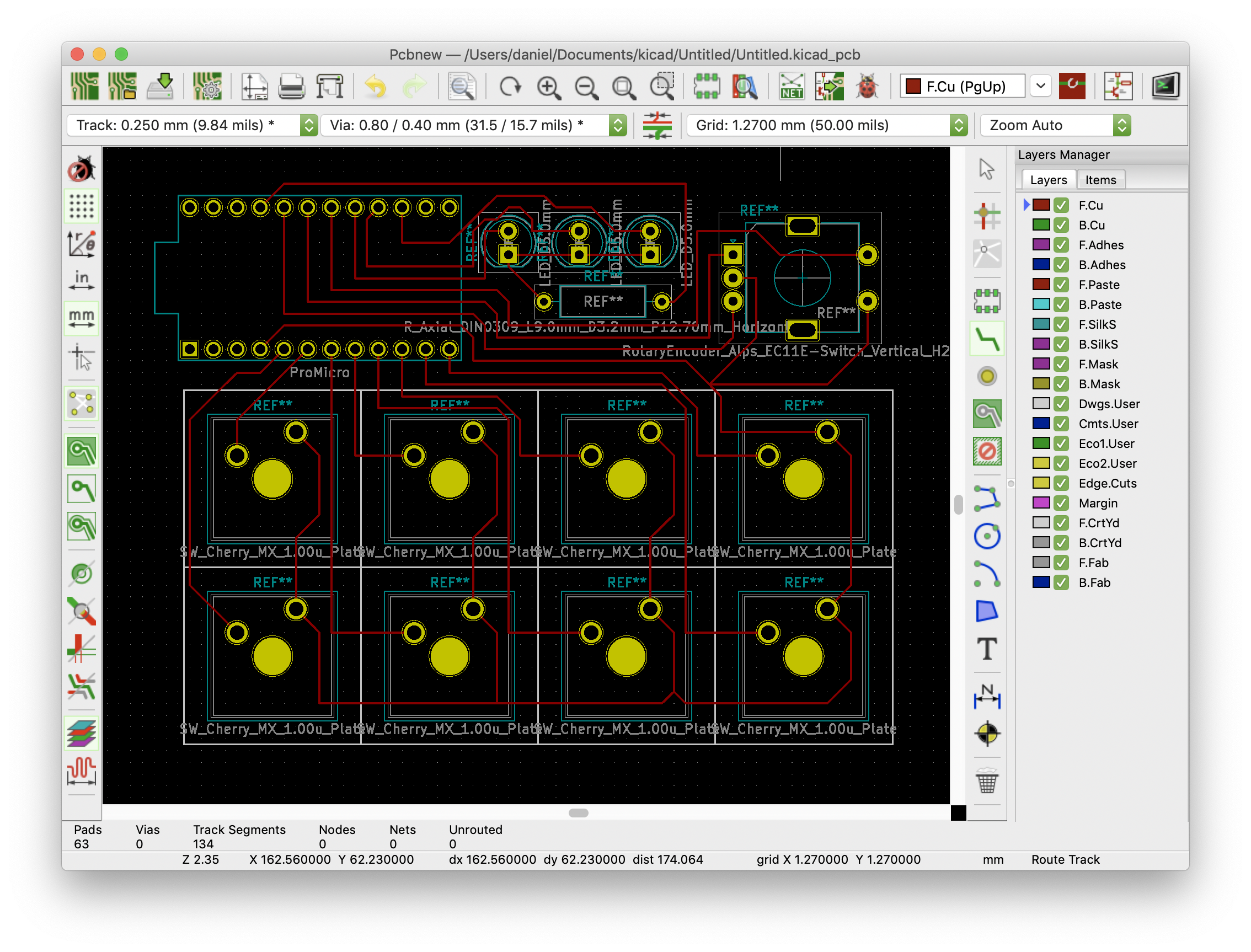
So at this point I was thinking of making a PCB of my own (like all the cool kids) and order it for cheap from one of the many PCB manufactures out there in China. So I was playing around with kicad. Nice thing is that you will find the Cherry MX PCB footprint already included in the parts library. But I quickly realized that the much needed footprint of the Arduino Pro Micro was not available by default. But fear not weary electronics adventurer GitHub is there to help: https://github.com/Biacco42/ProMicroKiCad. Adding this library allows you to plan your PCB. I wanted it to be as easy as possible therefore I chose to make it a single sided PCB which, if necessary, could be etched by hand at home.
Doing it the quick and dirty way
So at this point I was getting a bit impatient. When I start a new project I have all the enthusiasm but sadly paired with an unbearable impatience. Therefore, after browsing a bit more the interwebs I realized why bother in making a PCB when you can just solder a few cables to a handful of switches. There I found this beautiful project: https://www.partsnotincluded.com/diy-stream-deck-mini-macro-keyboard/. And here is where I decided to just stick with something simple as that and leave the PCB project for future me. But I knew I had to add some additional features to it.
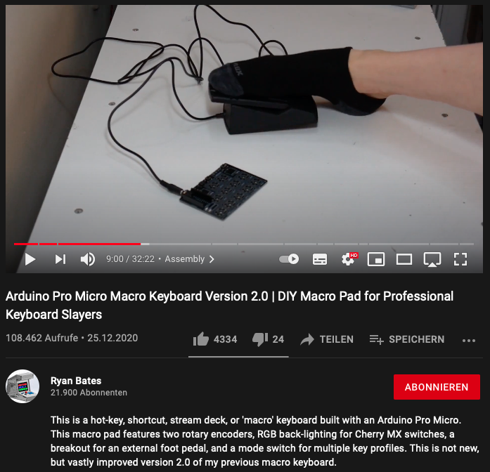
One of these additional features was absolutely clear after watching the above mentioned "Arduino Pro Micro Macro Keyboard Version 2.0" video. The excellent demonstration of a foot pedal switch in this video convinced me that I definitely needed one of these, too (although I have no real idea right now what for XD).
The second feature was a rotary encoder with click function. This will allow adjustment of volume and brightness and might be some zoom in/out help for certain programs like InkScape. On top of that I wanted to redesign the enclosure to make it fit next to my existing keyboard.
How though?!
Glad you asked. The how is rather simple. It required some CAD, some 3D printing, some wire crimping, soldering and eventually some simple coding.
Parts
A small list of things you will need to build this macro keyboard. I'm assuming that you have wire crimping stuff and soldering utensils at hand.
- 3x LEDs (5mm)
- 1x 330 Ohm resistor
- 1x Rotary encoder with click (amazon)
- 8x Mechanical switches (amazon)
- 8x Key caps (amazon)
- 1x 3.5 mm Headphone jack (amazon)
- 1x Arduino pro micro (amazon)
- 2x M3 20mm screws
- 1x Pedal switch (amazon)
These are no amazon affiliate links. I'm not earning anything. You're not being tracked. These are just examples of whta I used to build this macro keyboard. You're free to chose whichever components you find fitting.
Enclosure, switches, LEDs and rotary encoder
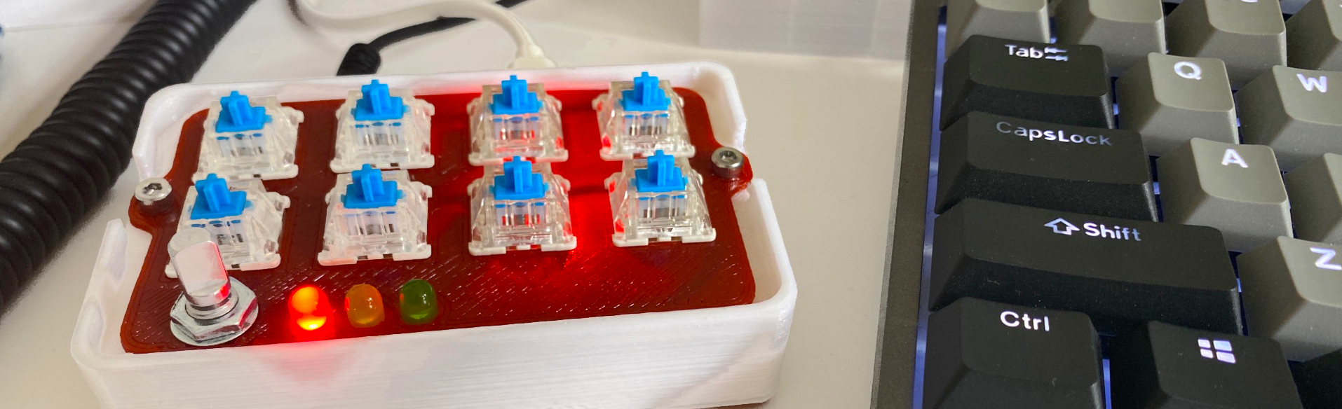
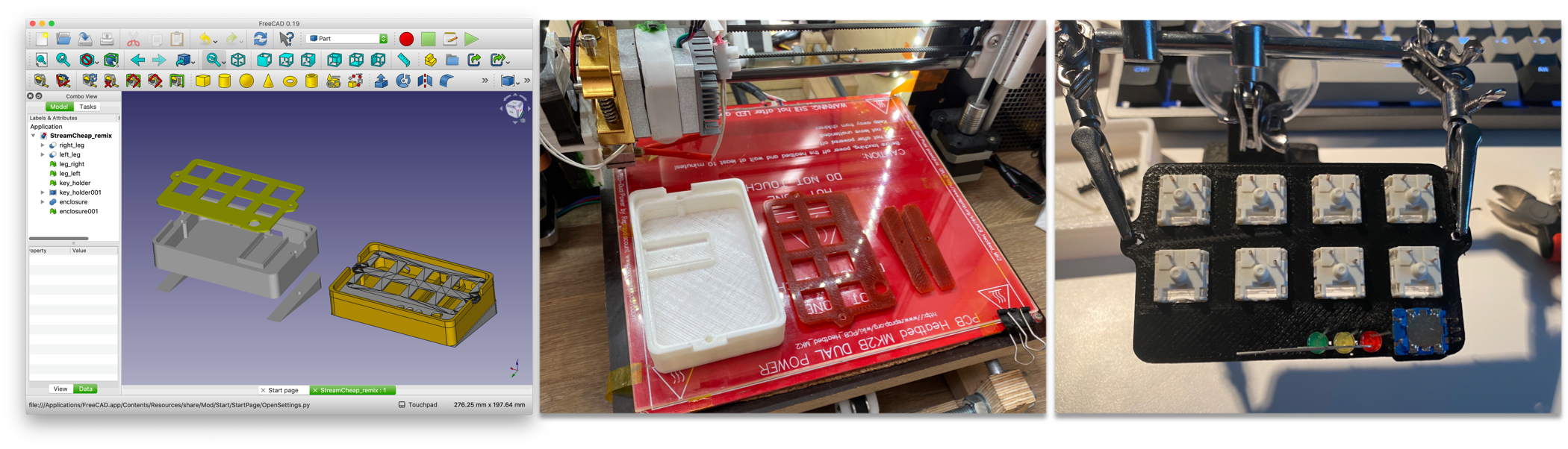
The "DIY Stream Deck (Mini Macro Keyboard)" project mentioned earlier had the .stl files for the switch holder plate and the enclosure included. For my project I designed a new enclosure and modified the available switch holder plate to fit a rotary encoder and three LEDs. After finishing the design I took my trashy but trusty 3D printer and fed it the .stl files to get the parts needed. Now that I had the switch holder top plate I started assembling the whole thing by popping in the switches, the LEDs and the rotary encoder. All .stl files can be downloaded on Thingiverse: https://www.thingiverse.com/thing:5165163
Wiring up the whole thing
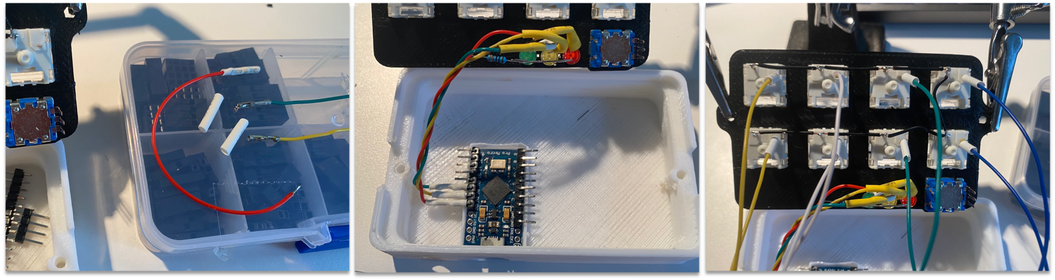
First thing that I did is to bend the ground pins of the LEDs and solder them together. Next, I added a 330 Ohm resistor to the ground of the LEDs (can be higher if you want it a bit darker). The three LEDs will later indicate which mode the rotary encoder is in. After that I prepped the ground connections for the switches. Measure twice, cut once. As you can see that didn't work out that well. I stripped these wires on both sides (2 - 3 mm) and soldered them to the switch pins connecting them all to a single ground.

As I planned to have in total 8x switches, 1x rotary click switch plus 1x amazing pedal switch (10 for the lazy ones) I was generous and gave every switch its own personal pin on our Arduino Pro Micro (also lazy because this is the easiest way to wire things u). So pop in the Arduino Pro Micro and start preparing the wires. In order to use the right amount of cable try to position the switches and the enclosure in a reasonable distance to each other. For the wires: I like to strip the cut wires on both sides and use a crimping tool and some heat shrink tube for the side that is plugged into the Arduino board. If you're dead certain that you won't change a thing after the assembly you can also solder the wires directly to the Arduino board.
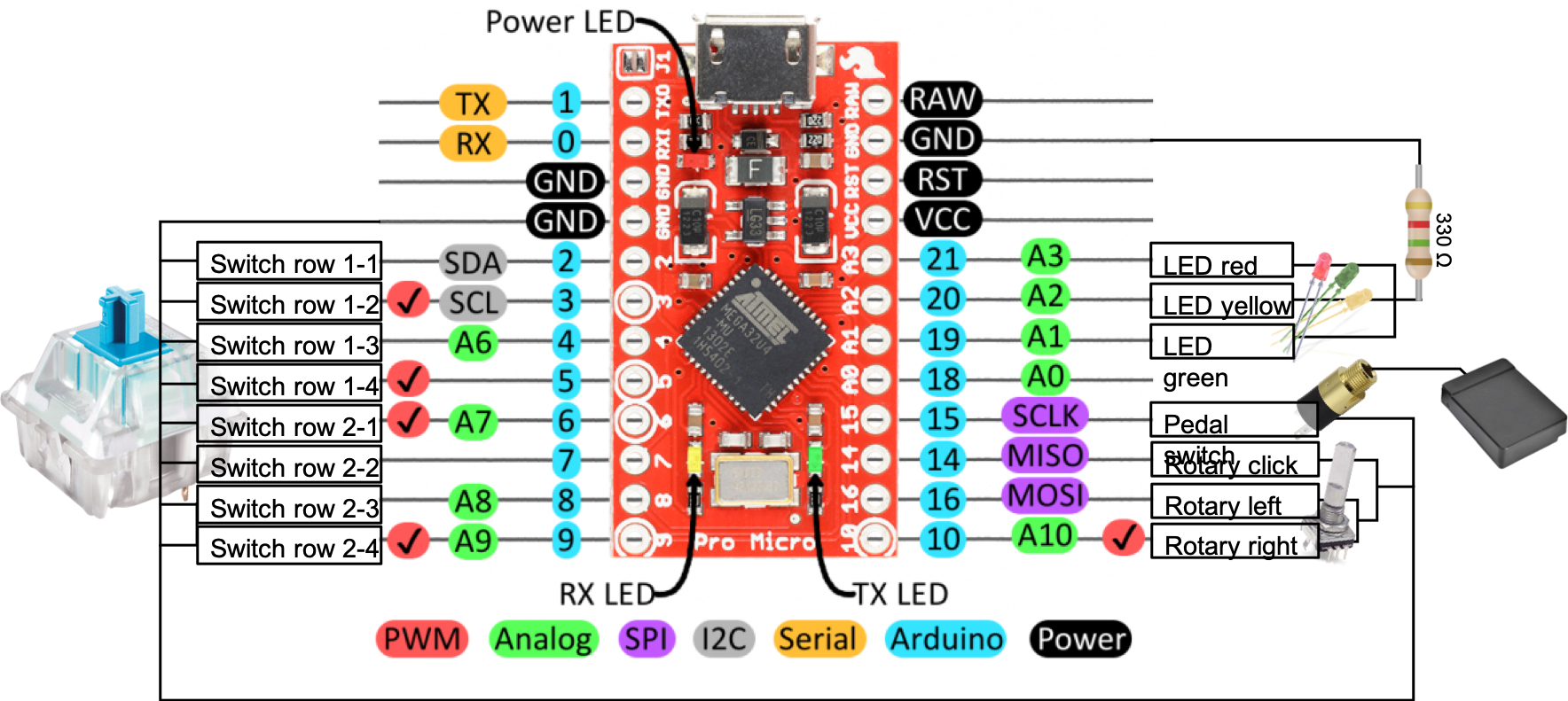
Now that all wires are where they are supposed to be we can start plugging everything into the arduino board. For that I made a little scheme that you can follow if you want to. As you can see I plugged the switches into the pins 2 to 9, the rotary encoder to 10,16 and 14, the pedal to 15 and the three LEDs to 19, 20 and 21. I used the same ground pin for the switches, rotary encoder and the pedal. The LEDs were connected to ground with a 330 ohm resistor.
Now everything needs to be cramped back into the housing. If you're like me and didn't pay much attention to the length of the cables you will now struggle a bit until you get annoyed and then you just press everyhting in with a moderate amount of force. The screw holes are designed to be small enough that the screw will thread itself in so no need to insert little brass threads to keep the top plate in place.
The code
After assembly I sat down and had a look at possible arduino libraries that would suit this project. First thing I came across was the keyboard library which worked but had some missing functionality. So after a bit of research I ended up with the HID-Project library. As we have connected the switches directly to the pins we need some software deboucing. For this I used the library ezButton. To make some sense out of the turning and clicking of the rotary encoder I used the RotaryEncoder library. These three libraries combined will make everything work magically with you doing only a minimum amount of coding.
In the first part we define all pins and include all the libaries. I'm using PlatformIO to program my arduino boards. But it is also possible to do this with the standard arduino IDE.
      #include <Arduino.h>
      #include <ezButton.h>
      #include <RotaryEncoder.h>
      #include <HID-Project.h>

      //Define the LED pins
      uint8_t LED_PINS[3] = { A1, A2, A3 };

      //Define the button pins as ezButtons
      ezButton KEY1_1(2);
      ezButton KEY1_2(3);
      ezButton KEY1_3(4);
      ezButton KEY1_4(5);
      ezButton KEY2_1(6);
      ezButton KEY2_2(7);
      ezButton KEY2_3(8);
      ezButton KEY2_4(9);
      ezButton ROT1_1(14);
      ezButton PED1_1(15);

      //Define rotary pins
      #define ROT_TURN1 10
      #define ROT_TURN2 16

      //Define the rotary encoder type (see documentation of RotaryEncoder for the exact type you need)
      RotaryEncoder encoder(ROT_TURN1, ROT_TURN2, RotaryEncoder::LatchMode::FOUR3);

      //Define the counter for different rotary encoder modes; we will use 3 modes later
      // - LEDs red, yellow, green
      int count = 0;
We need to create a function for the rotary encoder:
    //Function for rotary encoder position
    void checkPosition()
    {
      encoder.tick(); // just call tick() to check the state.
    }
Next step is to initialize all the pin modes and setting the debounce time for the buttons. This will give us a nice single click for each button press.
    //Initialize all the things
    void setup() {
      //Start the serial communication for debugging
      Serial.begin(9600);

      //Set all LED pins to output
      for(int i = 0; i < 3; i++) {
            pinMode(LED_PINS[i], OUTPUT);
      }

      //Set 50 ms debounce for all keys
      KEY1_1.setDebounceTime(50);
      KEY1_2.setDebounceTime(50);
      KEY1_3.setDebounceTime(50);
      KEY1_4.setDebounceTime(50);
      KEY2_1.setDebounceTime(50);
      KEY2_2.setDebounceTime(50);
      KEY2_3.setDebounceTime(50);
      KEY2_4.setDebounceTime(50);
      ROT1_1.setDebounceTime(50);
      PED1_1.setDebounceTime(50);

      //Rotary turn
      attachInterrupt(digitalPinToInterrupt(ROT_TURN1), checkPosition, CHANGE);
      attachInterrupt(digitalPinToInterrupt(ROT_TURN2), checkPosition, CHANGE);

      //Start the keyboard dependencies from the HID-Project library
      Keyboard.begin();
      Consumer.begin();
    }
Now we're starting the loop. We define the ezButton loop for all the pins that are connected to buttons:
    //Loopy loop over all the things
    void loop() {
      //Start the ezButton loop for all keays
      KEY1_1.loop();
      KEY1_2.loop();
      KEY1_3.loop();
      KEY1_4.loop();
      KEY2_1.loop();
      KEY2_2.loop();
      KEY2_3.loop();
      KEY2_4.loop();
      ROT1_1.loop();
      PED1_1.loop();
Next we check if any of the buttons has been pressed. For the first three buttons I added some example output from the HID-project library. There is plente more and any combinations of standard buttons is supported so that any macro imaginable can be created.
    //Check if any button has been pressed:
    // - First row buttons:
    if(KEY1_1.isPressed()){
      Serial.print("Key1_1!");
      //Example play pause
      Consumer.write(MEDIA_PLAY_PAUSE);
    }
    if(KEY1_2.isPressed()){
      Serial.print("Key1_2!");
      //Example previous
      Keyboard.press(MEDIA_PREVIOUS);
    }
    if(KEY1_3.isPressed()){
      Serial.print("Key1_3!");
      //Example next
      Keyboard.press(MEDIA_NEXT);
    }
    if(KEY1_4.isPressed()){
      Serial.print("Key1_4!");
    }

    // - Second row buttons:
    if(KEY2_1.isPressed()){
      Serial.print("Key2_1!");
    }
    if(KEY2_2.isPressed()){
      Serial.print("Key2_2!");
    }
    if(KEY2_3.isPressed()){
      Serial.print("Key2_3!");
    }
    if(KEY2_4.isPressed()){
      Serial.print("Key2_4!");
    }
    if(PED1_1.isPressed()){
      Serial.print("Pedal1_1!");
    }
The rotary encoder needs some special treatment as we want to switch between three different modes (red, yellow, green). First we check if the button is pressed and after that we change to the next button mode. By checking the pinmode of the three LEDs we then execute either volume +/-, brightness +/- or zoom in/out (Inkscape).
      //Rotary encoder options:
      //  - Indicate the mode the rotary encoder is in right now
      digitalWrite(LED_PINS[count], HIGH);

      //Rotary encoder key press:
      // - If rotary encoder button is pressd change to next mode
      if(ROT1_1.isPressed()){
        Serial.print(count);
        Serial.print("ROT1_1!");

        if(count < 2){
          count = count + 1;
          Serial.print(count);
          digitalWrite(LED_PINS[count], HIGH);

          if(count-1 != -1){
            digitalWrite(LED_PINS[count-1], LOW);
          }

        }else{
          digitalWrite(LED_PINS[count], LOW);
          count = 0;
          digitalWrite(LED_PINS[count], HIGH);
        }
      }

      //Check the PIN mode and do accordingly:
      // - Mode 1 (red)
      // - Volume control
      if (digitalRead(LED_PINS[0]) == HIGH){
        static int pos = 0;
        encoder.tick();

        int newPos = encoder.getPosition();
        if (pos != newPos) {
          if (newPos > pos){
            Consumer.write(MEDIA_VOL_DOWN);
          }else if(newPos < pos){
            Consumer.write(MEDIA_VOL_UP);
          }
          Serial.print("pos:");
          Serial.print(newPos);
          Serial.print(" dir:");
          Serial.println((int)(encoder.getDirection()));
          pos = newPos;
        }
      }

      // - Mode 2 (yellow)
      // - Brightness control
      if (digitalRead(LED_PINS[1]) == HIGH){
        static int pos = 0;
        encoder.tick();

        int newPos = encoder.getPosition();
        if (pos != newPos) {
          if (newPos > pos){
            Consumer.write(CONSUMER_BRIGHTNESS_UP);
          }else if(newPos < pos){
            Consumer.write(CONSUMER_BRIGHTNESS_DOWN);
          }
          Serial.print("pos:");
          Serial.print(newPos);
          Serial.print(" dir:");
          Serial.println((int)(encoder.getDirection()));
          pos = newPos;
        }
      }

      // - Mode 3 (green)
      // - Zoom in/out Inkskape
      if (digitalRead(LED_PINS[2]) == HIGH){
        static int pos = 0;
        encoder.tick();

        int newPos = encoder.getPosition();
        if (pos != newPos) {
          if (newPos > pos){
            Keyboard.press(KEY_LEFT_CTRL);
            Keyboard.press(KEY_EQUAL);
            Keyboard.releaseAll();
          }else if(newPos < pos){
            Keyboard.press(KEY_LEFT_CTRL);
            Keyboard.press(KEY_MINUS);
            Keyboard.releaseAll();
          }
          Serial.print("pos:");
          Serial.print(newPos);
          Serial.print(" dir:");
          Serial.println((int)(encoder.getDirection()));
          pos = newPos;
        }
      }
    }
In a short while I will put together a GitHub repository of all the files for the 3D models and the code necessary for working with the macro keyboard. If you have questions on this project write me an email or connect with me on my IRC server in the channel #tinker! :)